High‑Density Polyethylene (HDPE) T60-800

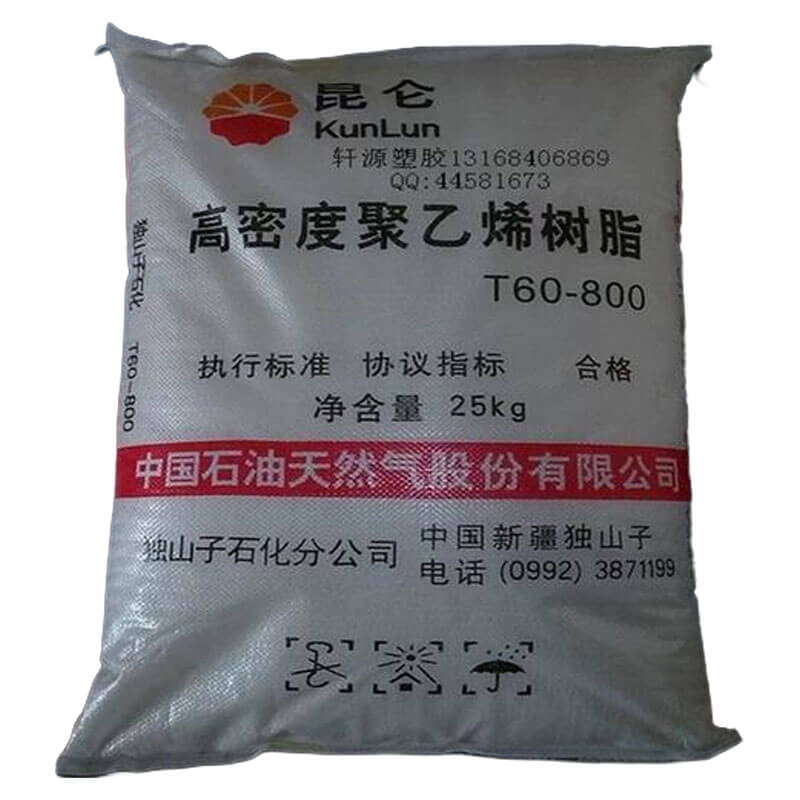
    • Product Name: High‑Density Polyethylene (HDPE) T60-800
    • Factroy Site: No. 6 Beijing Road, Dushanzi, Xinjiang
    • Price Inquiry: sales4@ascent-chem.com
    • Manufacturer: PetroChina Dushanzi Petrochemical Company
    • CONTACT NOW
    Specifications
    HS Code 169254
    Density 0.955 g/cm³
    Melt Flow Rate 190c 2 16kg 60 g/10min
    Tensile Strength At Yield 25 MPa
    Elongation At Break 50%
    Flexural Modulus 900 MPa
    Izod Impact Strength Notched 23c 3 kJ/m²
    Shore Hardness D 64
    Melting Point 126 °C
    Vicat Softening Point 120 °C
    Heat Deflection Temperature 0 45mpa 65 °C
    Water Absorption 24h 0.01%
    Crystallinity 60%

    As an accredited High‑Density Polyethylene (HDPE) T60-800 factory, we enforce strict quality protocols—every batch undergoes rigorous testing to ensure consistent efficacy and safety standards.

    Packing & Storage
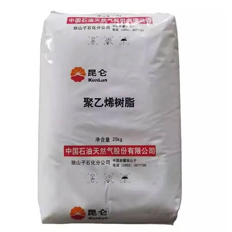
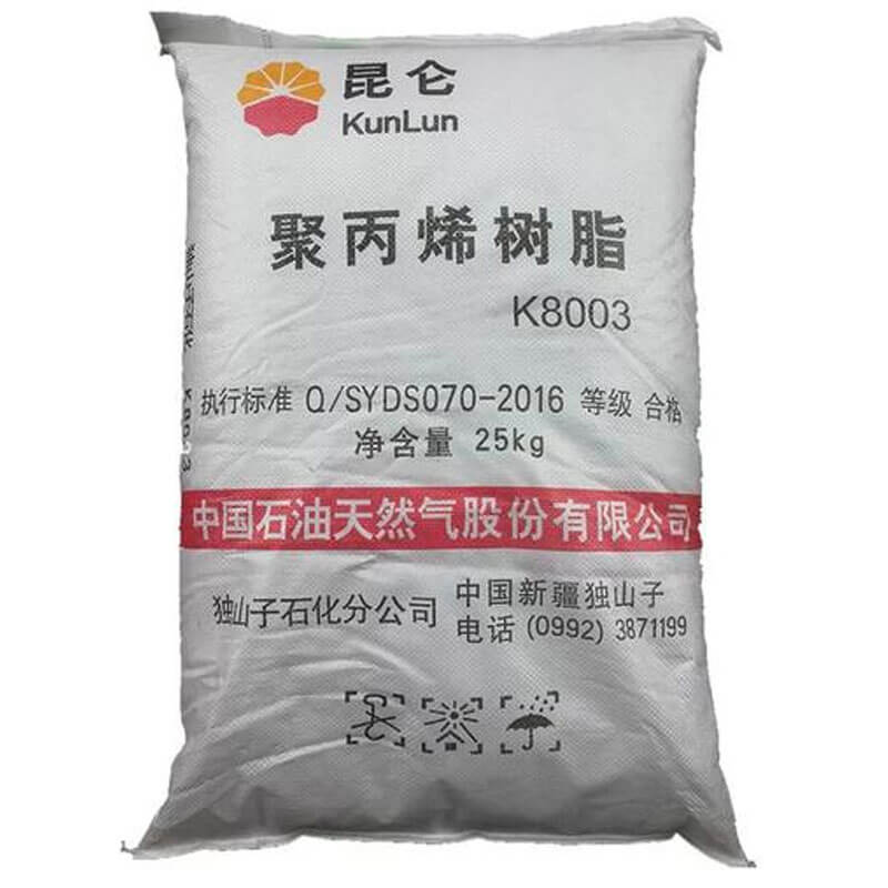
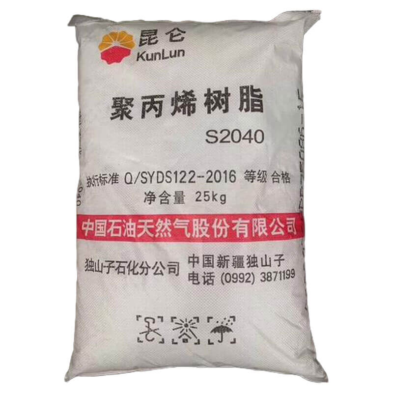
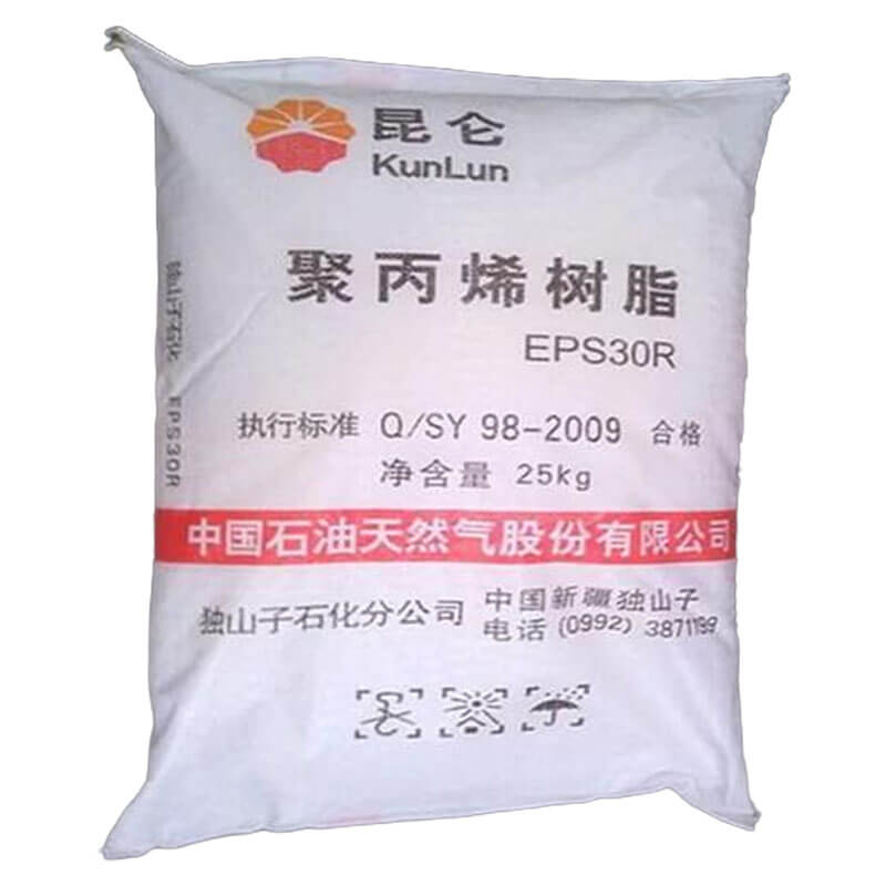
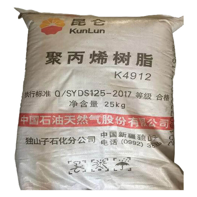
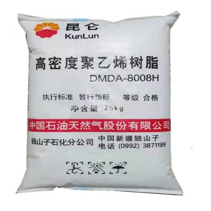
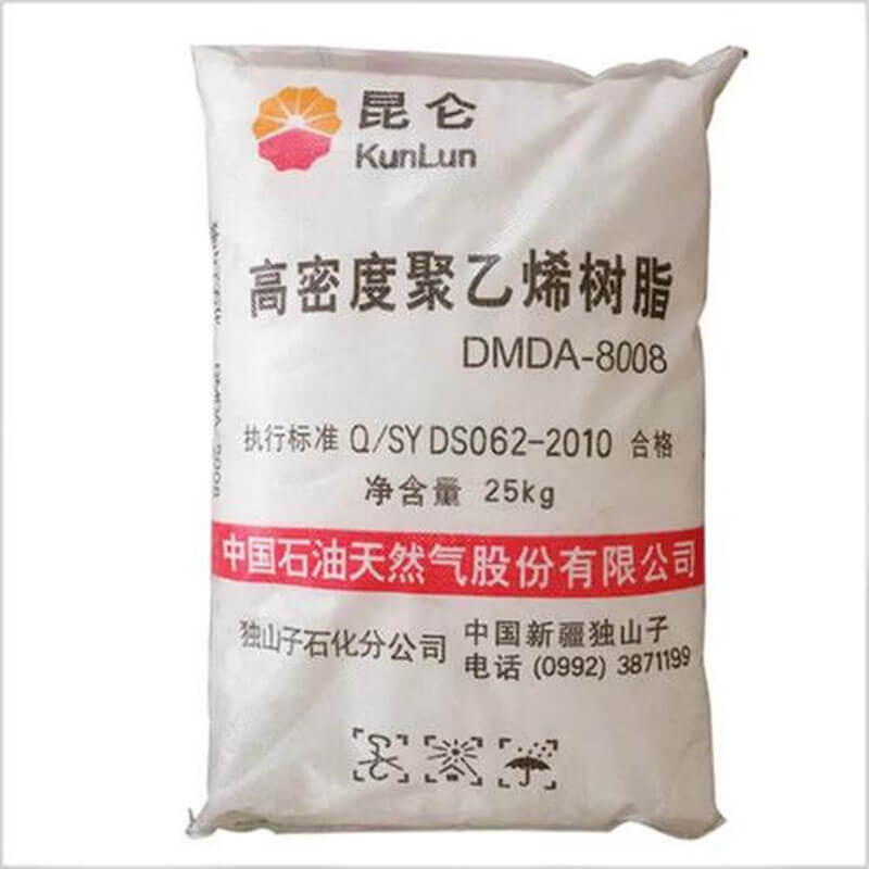
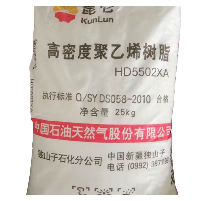
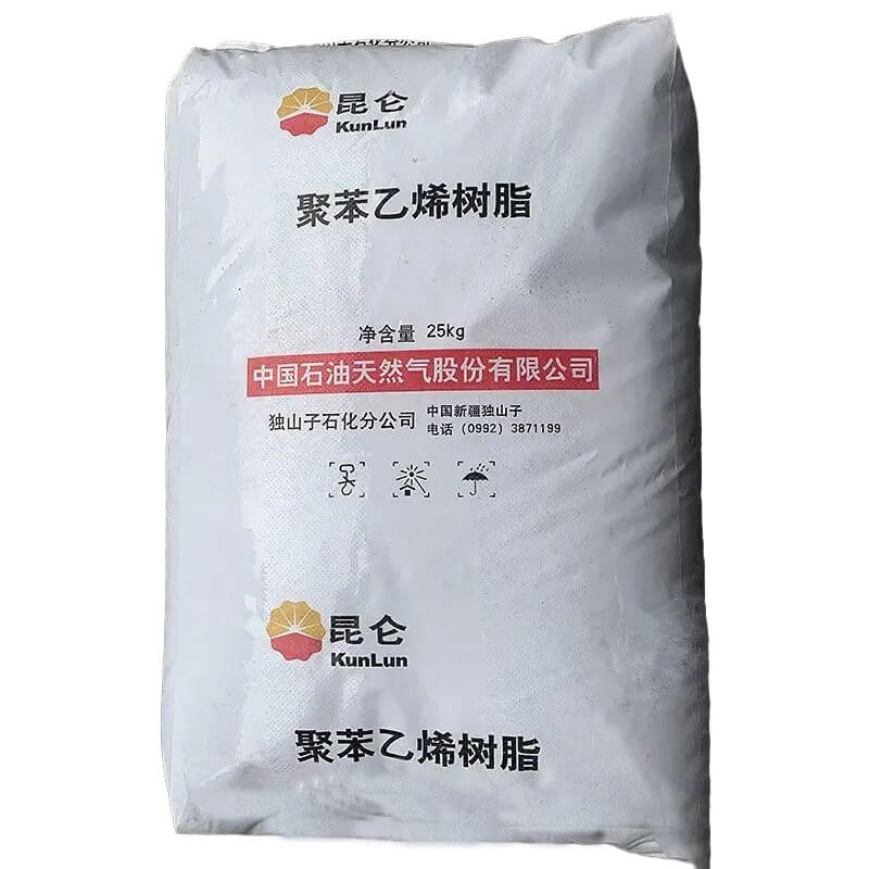
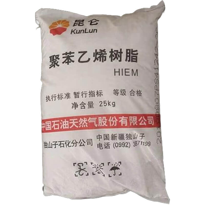
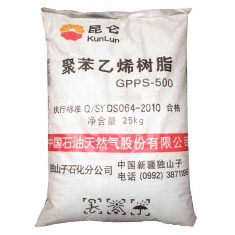
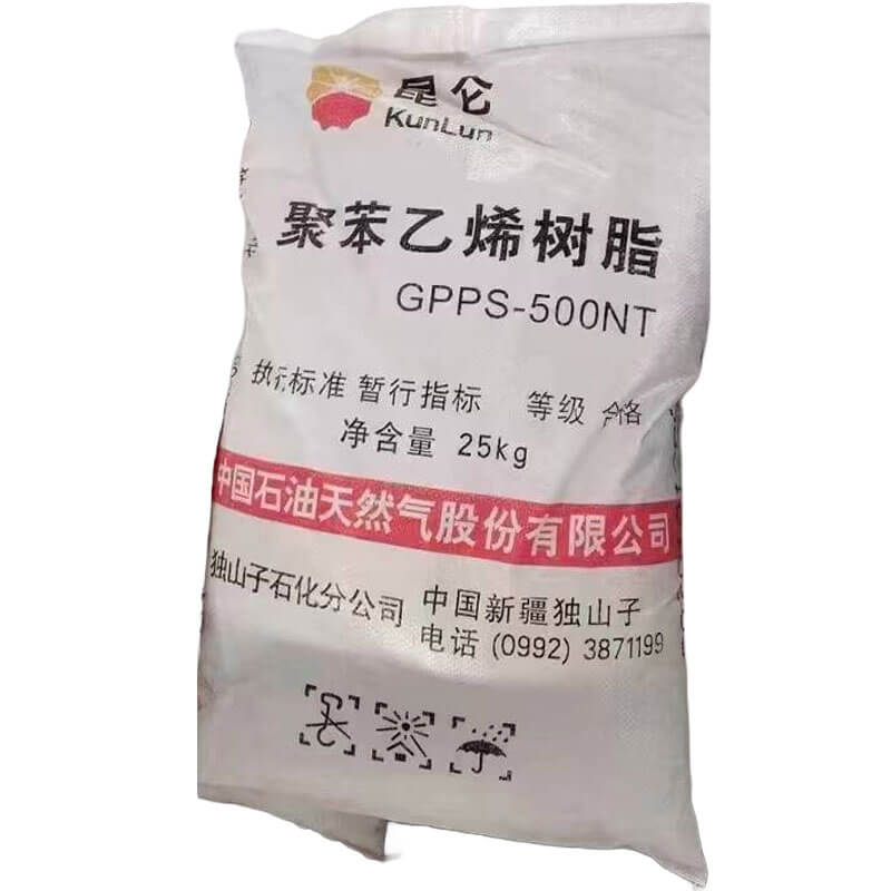
    Packing High-Density Polyethylene (HDPE) T60-800 is supplied in 25 kg moisture-resistant bags, palletized and wrapped for safe transport.
    Container Loading (20′ FCL) 20′ FCL container loading of High‑Density Polyethylene T60‑800 pellets in FIBC bags, palletized, and secured for safe transport.
    Shipping High-Density Polyethylene (HDPE) T60-800 ships as non-hazardous solid pellets in woven bags, FIBCs, or bulk hopper cars and containers. Protect from moisture and direct sunlight, keep clean to avoid contamination, and store at moderate temperatures. No special dangerous-goods declaration required, but secure loads to prevent shifting.
    Storage Store High-Density Polyethylene (HDPE) T60-800 in a cool, dry, well-ventilated area away from direct sunlight, heat sources, and open flames. Keep original containers tightly sealed to prevent moisture pickup and contamination. Avoid dust accumulation; use appropriate grounding for transfers. No special hazardous storage requirements, but maintain good housekeeping and follow standard polymer handling practices.
    Shelf Life HDPE T60-800 has a long shelf life, typically indefinite when stored in a cool, dry, UV-protected area.
    Application of High‑Density Polyethylene (HDPE) T60-800

    HDPE T60-800 is an extrusion-grade high-density polyethylene characterized by a density of 0.960 g/cm³ and a melt mass-flow rate of 0.80 g/10 min under 190°C and 5.0 kg load. The pelletized resin is normally processed without pre-drying unless surface condensation has occurred, in which case pre-drying at 80°C for 2 h reduces moisture-related surface defects. The compound meets the PE100 minimum required strength class with a hydrostatic design basis of 10 MPa at 20°C for 50 years under ISO 9080:2022 and ISO 12162-1:2019. Incoming batch inspection on industrial extrusion lines typically verifies melt mass-flow rate within ±0.05 g/10 min and density within ±0.002 g/cm³ before silo transfer. The following scenarios are restricted to downstream sectors in which this grade is commercially deployed: municipal pressure pipe, gas distribution, industrial slurry pipe, geothermal ground loops, and underground cable duct.

    Test methodParameterConditionApplication qualification function
    ISO 1133-1:2022Melt mass-flow rate190°C / 5.0 kg0.80 g/10 min target; verifies extrusion batch consistency
    ISO 1183-1:2019Density23°C0.960 g/cm³ target; controls crystallinity and stiffness
    ISO 6964Carbon black content and dispersionAshing at 550°C2.0–2.5 wt% dispersed carbon black; agglomerate size below 20 µm
    ISO 11357-6Oxidation induction time200°C, oxygen≥20 min typical stabilization threshold for long-term thermal resistance
    ISO 9080:2022 / ISO 12162-1:2019Minimum required strength20°C, 50 years10 MPa, PE100 classification
    ISO 13479:2022Notched pipe slow crack growth80°C hydrostaticNo failure before product-standard specified time limit

    What Limits Hydrostatic Design Life in Potable Water Mains Made from T60-800?

    Compounding for potable water pressure pipe is based on T60-800 at 95.0–97.0 wt% with carbon black masterbatch let-down at 3.0–5.0 wt% to yield a final dispersed carbon black content of 2.0–2.5 wt% under ISO 6964. A hindered phenolic/phosphite antioxidant package is added at 0.10–0.30 phr together with 0.05–0.15 phr calcium stearate as acid scavenger; the pigment-free natural compound is avoided for above-ground storage unless the pipe is co-extruded with a black protective layer. Production on grooved-feed single-screw extruders with L/D ratio 30:1–36:1 uses barrel temperatures from 180°C to 220°C, die-head temperature 200–215°C, and vacuum calibration at -0.3 to -0.6 bar. Melt temperature is held between 190°C and 230°C; lower temperatures increase head pressure and risk incomplete fusion at butt-weld joints, while higher temperatures accelerate oxidation and shift the notched slow crack growth curve. Terminal products include blue or black with blue identification stripes PE100 SDR 11 PN16 and SDR 17 PN10 pipes from 20 mm to 1,200 mm OD, tested to ISO 4427-1:2019, ISO 4427-2:2019, EN 12201-2:2011+A1:2018, and ASTM D3350 cell class PE 445574C. Hydrostatic design basis is 10 MPa at 20°C for 50 years; slow crack growth is verified by ISO 13479:2022 notched pipe testing at 80°C, and rapid crack propagation is excluded by ISO 13477 S4 testing at 0°C for wall thicknesses above 15 mm. The pressure rating must be derated above 20°C according to ISO 13761-1, and continuous exposure to chlorine dioxide above 0.5 mg/L requires an oxidative-resistance evaluation beyond standard PE100 water pipe practice.

    Gas distribution pipe extrusion with T60-800 is configured as co-extruded black pipe with yellow identification stripes rather than monolayer yellow pipe, because the yellow pigment alone does not provide adequate UV stabilization for above-ground storage. The compound formulation uses 2.0–2.5 wt% carbon black in the main layer and a yellow masterbatch applied to the stripe at 2.0–4.0 wt% let-down; the yellow pigment is heat-stabilized for continuous runs at 220–230°C to prevent die-lip deposition and batch-to-batch colour drift. A 30:1–36:1 L/D grooved-feed single-screw extruder is operated with melt pressure at the breaker plate not exceeding 35 MPa, melt temperature 200–225°C, and downstream cooling water between 15°C and 40°C. Terminal products are SDR 11 and SDR 17.6 PE100 mains and service pipes from 16 mm to 630 mm OD for natural gas distribution, qualified under ISO 4437-2:2014, EN 1555-2:2021, and ASTM D2513. Minimum required strength is 10 MPa at 20°C for 50 years; rapid crack propagation S4 testing per ISO 13477 at 0°C is applied to wall thicknesses greater than 15 mm. The assembled pipe must not be exposed to aromatic hydrocarbons or liquid hydrocarbon condensates, which reduce the slow crack growth threshold; published data for prolonged exposure of this grade to odorant-saturated methane above 2 bar partial pressure is limited. Electrofusion joining requires mechanical scraping of the oxide layer, alignment within 0.5 mm diametric clearance, and controlled fusion time to avoid cold-zone weld failures.

    Industrial Slurry and Tailings Pipe: Abrasion Limits and Thick-Wall Processing

    Mining and dredge slurry transport uses T60-800 in solid-wall thick-wall pipe where PE100 slow crack growth resistance is required for long-term pressure service. The compound is stabilized with 2.0–2.5 wt% carbon black and 0.10–0.25 phr of a processing antioxidant package; mineral filler abrasion modifiers are generally excluded because filler agglomerates above 10 µm initiate slow crack growth and reduce ISO 13479:2022 notched pipe lifetimes. Extrusion of wall thicknesses above 60 mm requires internal mandrel cooling and screw speeds restricted to 20–40 rpm to prevent centre-line void formation; die-head temperature is maintained at 195–210°C, vacuum calibration at -0.4 bar, and stepped cooling from 40°C to 20°C lowers residual stress before cutting. Terminal products include tailings discharge mains, dredge slurry lines, and heap-leach solution pipes from 90 mm to 1,600 mm OD. Conformance is verified against ISO 4427-2 for pressure hold, ASTM D3350 PE4710 cell classification, and project-specific slurry erosion testing on machined pipe specimens. Erosive wear in 20 wt% silica slurry with particle size 200–500 µm is strongly velocity-dependent; published data for T60-800 in turbulent slurry above 5 m/s is limited, so project-specific wear testing is required for flows above this threshold. The operational boundary excludes continuous exposure to oxidising acids, aromatic solvents, and slurry temperatures above 60°C unless chemical resistance is validated under ISO/TR 10358 and the pressure rating is derated under ISO 13761-1.

    Geothermal ground-loop pipe made from T60-800 is extruded as high-density polyethylene pressure coil for ground-source heat pump circuits. The compound contains 2.0–2.5 wt% carbon black for UV stability during above-ground stockpiling and 0.10–0.20 phr long-term thermal stabilizer to preserve slow crack growth resistance through repeated thermal cycling. Production is performed on a 30:1 L/D single-screw extruder with melt temperature 190–215°C; outer diameter tolerance is maintained within ±0.1 mm through ultrasonic wall-thickness scanning immediately downstream of the vacuum calibration sleeve. Terminal products include SDR 11 and SDR 13.5 U-loop heat-exchange circuits in 25 mm, 32 mm, and 40 mm OD, header pipes to 160 mm OD, and vertical borehole grouted loops. Standards governing the pipe are ASTM D3035 and CSA B137.1; project specifications may reference IGSHPA installation guidelines for grouted loop fields. Hydrostatic design basis remains 10 MPa at 20°C; at 40°C the pressure rating is reduced by a factor of 0.74 under ISO 13761-1. Continuous operation above 60°C is outside the rated envelope, and direct contact with glycol formulations above 30 vol% requires specific lifetime validation against stress cracking and extraction.

    When T60-800 Is Used in Cable Duct and Optical-Fiber Conduit Extrusion

    Underground power and telecommunication duct extrusion uses T60-800 to meet impact resistance at low ambient installation temperatures and to maintain circular stiffness during cable pulling. The compound is let down with 5.0–6.0 wt% carbon black masterbatch to achieve 2.0–2.5 wt% dispersed carbon black and includes 0.10–0.20 phr antioxidant; no halogenated flame retardant is used in standard buried duct because it is not required by the buried-conduit thermal envelope and would complicate recycling. Extrusion is performed on 25:1–30:1 L/D single-screw lines with screen packs at 80/120/80 mesh, melt temperature 200–220°C, and melt pressure below 30 MPa to avoid excessive shear heating. The finished duct is smooth-wall or corrugated, from 40 mm to 250 mm OD, with inner-wall roughness held below 0.05 mm for cable blowing. Compliance follows EN 61386-24 for buried conduit and UL 651A for underground raceway when required. Terminal products include HDPE telecom duct, fibre-optic microduct bundles, and low-voltage cable raceways. Continuous service above 70°C is outside the rated envelope, and installations near external heat sources require thermal backfill or derating.

    Free Quote

    Competitive High‑Density Polyethylene (HDPE) T60-800 prices that fit your budget—flexible terms and customized quotes for every order.

    For samples, pricing, or more information, please contact us at +8618136850665 or mail to sales4@ascent-chem.com.

    We will respond to you as soon as possible.

    Tel: +8618136850665

    Email: sales4@ascent-chem.com

    Inquiry

    Get Free Quote of PetroChina Dushanzi Petrochemical Company

    Flexible payment, competitive price, premium service - Inquire now!

    Certification & Compliance
    More Introduction

    High-density polyethylene (HDPE) T60-800 is an injection-moulding grade whose designation encodes a nominal density of 0.960 g/cm³ and a melt mass-flow rate of 8.0 g/10 min when determined at 190 °C under a 2.16 kg load. The grade is assigned to thin-wall food containers, caps and closures, housewares, toys, and general-purpose moulded articles in which cavity filling speed and cycle-time reduction dominate tooling economics. The material is supplied as pelletized resin with controlled pellet flow, and its molecular architecture favours low melt elasticity and moderate shear thinning rather than the high melt strength required for blow-moulding or the high long-term hydrostatic strength required for pressure-pipe service. This distinction is critical: HDPE T60-800 does not carry a long-term hydrostatic strength classification under ISO 9080 or ISO 4427, and it is not intended for gas or water-pressure pipe.

    What Property Profile Defines HDPE T60-800 in Injection Moulding?

    Manufacturer datasheets list typical tensile yield strength of 28 MPa under ASTM D638, flexural modulus of approximately 1,350 MPa under ASTM D790, and notched Izod impact at 23 °C of 30 J/m under ASTM D256. Vicat softening temperature is reported at 124 °C under ASTM D1525, and low-temperature brittleness is typically below −70 °C under ASTM D746. Density is 0.960 g/cm³ under ASTM D1505 or ISO 1183-1. The melt flow ratio, measured as the high-load to standard-load melt index, indicates narrow molecular weight distribution suitable for injection moulding. Published environmental stress crack resistance values under ASTM D1693 are not always listed for this melt-flow class; where data are absent, comparative ESCR claims should not be made without direct testing.

    On hydraulic and toggle injection machines with screw L/D ratios of 20:1 to 24:1 and compression ratios of 2.0:1 to 2.5:1, melt temperatures from rear zone to nozzle are typically profiled from 180 °C to 230 °C, with nozzle temperature not exceeding 250 °C. Mold temperatures of 10–40 °C are used; lower mold temperatures accelerate skin solidification but increase the risk of visible flow lines and weld-line weakness in thin sections. Injection pressure at the screw tip commonly ranges from 70 MPa to 120 MPa depending on flow length to wall thickness ratio. Venting depth should not exceed 0.02–0.03 mm for high-flow HDPE to avoid flash. Back pressure is maintained below 1.5 MPa, and screw rotation speed is typically limited to 80–120 min⁻¹ to avoid shear heating beyond the target melt temperature.

    When Melt Flow Index Exceeds 8 g/10 min in Thin-Wall Tooling

    The high melt-flow value creates a measurable drop in injection pressure across narrow flow paths. For a wall thickness of 0.6 mm and flow length of 120 mm, published spiral-flow data for this melt-flow class generally indicate adequate filling at melt temperatures above 210 °C; however, published data for this specific grade’s spiral-flow length is limited, so tooling should be gated and vented conservatively. Hot-runner manifolds with valve gating are preferred because the low melt elasticity reduces valve-pin drool. Thermal stability is adequate for residence times below 5 min at 240 °C; extended hold times or dead spots in the manifold raise the risk of chain scission and yellowing.

    Flow-induced orientation in thin-wall sections creates a skin-core morphology. The skin layer quenches rapidly against the mold wall; the core continues to crystallize at lower shear. This results in anisotropic shrinkage, with typical linear mold shrinkage values of 1.5–2.5% under ASTM D955, depending on wall thickness and packing pressure. Packing pressure should be sequenced to maintain gate freeze after cavity filling. For this grade, gate freeze time is short due to high melt flow, so decoupled moulding strategies using cavity-pressure transducers are used on production lines to prevent sink marks in bosses and ribs. If cavity pressure falls below 40 MPa before gate freeze, sink-mark depth increases measurably in sections thicker than 2 mm.

    Comparative Stiffness and ESCR Limitations Against Low-Melt-Index Pipe Grades

    When HDPE T60-800 is compared with a pipe-grade HDPE having a melt flow index below 0.5 g/10 min and density of 0.950 g/cm³, the flexural modulus of T60-800 is typically higher by 15–30%. The trade-off is lower melt strength and reduced environmental stress cracking resistance. Pipe-grade HDPE is classified as PE100 or PE80 under ISO 12162, with a minimum required strength of 10 MPa or 8 MPa at 50 years under ISO 9080 regression. Injection-moulding HDPE T60-800 is not tested to this protocol; its ESCR under ASTM D1693 may be substantially lower than values reported for bimodal pipe resins, depending on stress-cracking agent and notching conditions. Consequently, applications involving continuous internal pressure, strong detergents, or long-term outdoor stress should not be selected without direct comparative testing.

    Compared with a medium-density polyethylene of density 0.935 g/cm³, T60-800 provides higher top-load strength for closures but lower puncture impact at freezing temperatures. Cap liners may require elastomer modification if cold impact below −20 °C is specified. The unfilled resin is generally assessed for food-contact compliance in the United States under 21 CFR 177.1520 as an olefin polymer, subject to end-use extractive limitations. European converters must verify the final article under Regulation (EU) No 10/2011 for overall migration and specific migration limits. The grade is not intentionally formulated with lead, cadmium, mercury, hexavalent chromium, polybrominated biphenyls, or polybrominated diphenyl ethers; compliance with Directive 2011/65/EU is supported by supplier material declarations. Under REACH Regulation (EC) No 1907/2006, the polymer itself is exempt from registration as such, although monomer and additive substances in the formulation are registered.

    Compliance checklist matrix for unfilled HDPE T60-800
    Regulation or standard Scope Typical assessment
    21 CFR 177.1520 U.S. food-contact olefin polymers Applicable for olefin polymers; end-use extraction limits apply
    Regulation (EU) No 10/2011 Plastic food-contact articles Converter-specific overall migration and specific migration limit verification required
    REACH (EC) No 1907/2006 Chemical registration and authorization Polymer exempt from registration; monomer/additive substances registered in supply chain
    Directive 2011/65/EU RoHS hazardous substance restrictions Not intentionally formulated with restricted heavy metals or flame retardants
    ASTM D4976-12a Polyethylene plastics specification Cell classification based on density and melt index applied

    Documented Warpage and Cycle-Time Boundaries in High-Speed Injection Moulding

    Cycle time advantages with high melt-flow HDPE are limited by cooling time rather than injection time. At a wall thickness of 1.5 mm, cooling time estimated from part temperature at ejection below 80 °C is typically 8–12 s. Warpage in flat lids and caps is controlled when differential shrinkage across the part remains below 0.3%; differential shrinkage above 0.6% produces measurable out-of-plane distortion. Conformal cooling or cooling channels positioned at 8–12 mm from the cavity surface are required to maintain dimensional consistency in multi-cavity tools. Parts ejected above 80 °C may continue to shrink in storage and show dimensional drift exceeding 0.2% after 24 h. On production-scale stack molds with 8+8 cavities and valve-gated hot runners, clamp force requirements are determined by projected area and cavity pressure. For HDPE T60-800, a projected area of 600 cm² with estimated cavity pressure 40 MPa requires clamp force near 1,200 kN. Flash begins when cavity pressure exceeds 70 MPa on tools with vent depths greater than 0.03 mm. Short shots occur on thin ribs when melt temperature at the nozzle falls below 210 °C; the resulting hesitation marks are detectable as surface striations perpendicular to flow. This failure mode is remediated by increasing injection velocity to 120–200 mm/s rather than by raising nozzle temperature alone.

    Moisture uptake of HDPE pellets is generally low, but wet storage above 60% relative humidity or condensation on pellet surfaces can generate surface defects in moulded parts. Pre-drying in a desiccant dryer at 60–80 °C for 2 h is recommended after outdoor or uncontrolled storage. Regrind addition is typically limited to 20 wt% to maintain melt-flow uniformity and color. The material is incompatible with strong oxidizing acids and should not be exposed to ketone-based cleaning solvents at elevated temperature; approved purging compounds should be used to avoid cross-contamination with PVC or acetal resins.